Swami Vivekananda set the tone at the world religion congress stage, which has been a masterpiece of practical demonstration of Emotional Intelligence (EI)
AIR INTAKE FILTRATION SYSTEM – MOST IMPORTANT FOR RELAIBILITY OF GAS TURBINE POWER PLANT

Bibek Roy
Introduction:
Gas turbine (GT) combined cycle or simple cycle (SC) power plants are very efficient and clean way of power generation.
Gas Turbine Combined Cycle Power Plants (CCPP) are the most efficient power plants in the world. Efficiency of GT CCPP is as high as 65% in modern heavy-duty gas turbines.
Combined cycle power plant consists of Gas Turbine & compressor mounted in a single shaft, Heat Recovery Steam Generator (HRSG) and Steam Turbine (ST). Together this system is called Combined Cycle Power Plant (CCPP).
As air and fuel are the two main sources of combustion, hence quality of the air ingested by the GT air compressor plays very important role.
Poor air quality can damage the GT air compressor blades and can cause severe over heating effect in the gas turbine hot section components.
What is Gas Turbine (GT) air intake filtration (AIF)?
Gas turbines need air & fuel for combustion. Fuel is generally natural gas (NG) which contains approximately 94% of Methane.
Hot flue gas is generated from the GT After combustion and flue gas is diverted to HRSG for steam generation.
This steam from HRSG is then supplied to the Steam Turbine to generate power.
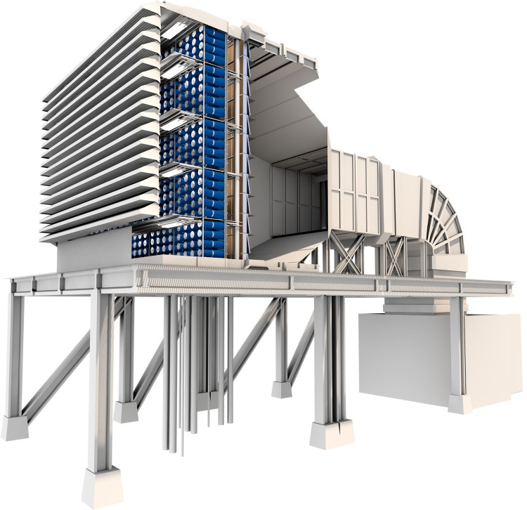
As air is one of the main inputs to the GT for combustion, hence a well-designed & efficient Air Intake Filtration (AIF) system is installed ahead of GT compressor section. (Add image of CCPP)
Clean air is the key to the higher efficiency of the axial air compressor and longer life of the GT hot gas path.
AIF also plays a key role for high availability of GT and low maintenance cost & down time.
Hence it is essential that Air Intake Filtration system must be well designed.
Typically, total air flow of a GE GT 9FA machine requires 11,277,63 CFM air flow which is considerable.
Why air intake filtration is required ?
Fuel costs in a Gas turbine plant is approximately 80 percent of the life cycle cost of electricity generation plant. Small gains in efficiency can mean huge savings.
Poor air quality will cause:
- Fouling in the compressor blades, thus causing less compressor efficiency. Fouling is caused by very minute dust particles and by the adherence of dust particles to airfoils and annulus surfaces.
Particles that cause fouling are typically smaller than 2 to 10 μm.
Smoke, carbon, oil mists, sea salts are some examples.
- Corrosion of the GT compressor blades. Corrosion is resulting from chemical oxidation of metal parts in presence of salts in the ingested air.
Corrosion in the compressor section is called “cold corrosion” and this is due to wet deposits of salts, acid, and aggressive gases such as chlorine and sulfides.
- Erosion is the process of “eating away” the blade material by abrasive action of dust particles in the ingested air.
Erosion is a non-reversible process.
The particles will impact the surface and remove very small amount of metal which cumulatively lead to changes in the geometry of the surface.
Particles of size 10 micron or more are responsible for erosion.
- If fouling / erosion/ corrosion is very high, blade damage can occur, thus causing unforeseen outage of the Gas Turbine plant.
- Foreign Object Damage (FOD).
Savings during operation can be achieved through improved compressor performance using High Efficiency Particulate Arrestor (HEPA) air intake filters.
HEPA filters have the ability to block the salt and water penetration.
Atmospheric air contains dust particles sizes ranging from PM-10, PM-2.5, PM-1, meaning of which has been given below:
The following particle size ranges are used in the ISO 16890 series for the listed efficiency values.
Optical particle diameter size ranges for the definition of the efficiencies, ePMx
| Efficiency | Size range, µm |
| ePM10 | 0,3 ≤ × ≤10 |
| ePM2,5 | 0,3 ≤ × ≤2,5 |
| ePM1 | 0,3 ≤ × ≤1 |
Size PM-10- Aerodynamic diameter < 10 micron
Size PM-2.5- Aerodynamic diameter < 2.5 micron
Size PM-1.0- Aerodynamic diameter < 1.0 micron
Apart from the above Nitrogen Di-oxide (NO2), Carbon monoxide (CO), Sulphur Di-oxide (SO2), Ozone, Methane (CH4), Ethane, Propane, Butane, Pentane, Hydrogen Sulphide(H2S), Hydrochloric acid(HCL), Sulphuric acid(H2SO4), Nitric acid(HNO3) & liquid droplets during rainy season and during foggy season, may also be present, depending on the demography of the region.
Above particulate matters and chemicals, when ingested inside the GT air compressor starts “Fouling”, “Erosion” & “Corrosion” on the compressor blades.
Turbine cooling air passages also starts plugging partially, causing insufficient cooling.
How Air Intake Filtration System Works:
Air requirement of a typical Gas Turbine is as follows:
Primary air = 30%. This air is passing through the combustion chamber for fuel combustion.
Secondary air = 65%. This air is passing through the holes in the inner shell and mixes with the hot exhaust gases.
Tertiary air = 5%. This air is used for turbine blade cooling and filming the blade surface.
Clean air enters in the intake filters from the surface and flows inside the filters towards clean area. All the dusts and salts are arrested in the filter.
New filters normally allow some more dusts to pass through the filters initially.
As the dust layer is growing up on the surface and inside the filter pleats, filtration become more effective.
Hence for better filtration, some dust layer on the filter surface is essential.
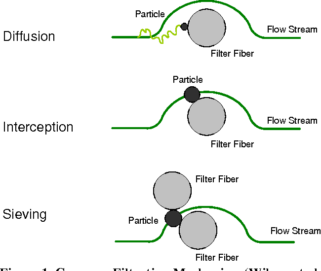
Filtration can be done in three modes:
- Diffusion – This is effective for very small particles typically less than 0.5 μm in size
- Interception – This type of filtration is suitable for medium-sized particles that are not large enough to leave the flow path due to inertia or not small enough to diffuse
- Sieving – This type of filtration is achieved when the space between the filter fibers is smaller than the particle itself, which causes the particle to be captured and contained.
However, when the dust layer grows up, differential pressure (DP) across the filter module section starts rising.
Hence in all Air Intake Filter systems, “Pulse Cleaning” system is installed.
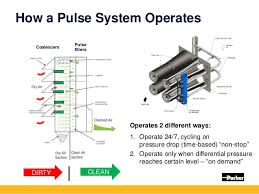
What is Pulse cleaning OR Self-cleaning system?
Pulse cleaning system works on a pre- set DP (Both in the higher side & in the lower side).
Once “set high DP” is achieved, Pulse cleaning system starts and “Puffs” the air from inside out.
This air puffing dislodges dusts from the surface of the air intake filters and thereby decreasing the DP.
Once set DP reaches pre-set “Normal” value, pulse cleaning stops automatically. Hence this type of filter is called “Self-cleaning” filters also.
Material of Construction of Air Intake Filters:
- 100% Synthetic (Polyester) – This media is preferred where ambient condition is sometimes highly humid or having huge fog during some seasons. Synthetic media has very high filtration efficiency.
- Mix of synthetic (Polyester)-Cellulose – This media is generally used where ambient condition is less humid. Cellulose has the lowest filtration efficiency.
These filters are having “Pleated” media.
Pleated media offers:
- High filtration efficiency
- High retention level
- Easy to clean
- High Air to Cloth ration
Type of filtration:
AIFs are of generally two types based on type of filtration:
- Surface loading – In this type of filters the particles collect on the surface of the filter.
Some of the particles can pass through the fiber material, but not enough to initiate replacement of the filters.
Surface loaded filters are most commonly used and self-cleaning systems are incorporated, because the dust can easily be removed with pulses of air once the filter differential pressure reaches a certain level.
Once the filter is cleaned, the pressure loss across the filter will be close to its original condition.
- Depth loading - Depth loading is the type of filtration where the particles are captured inside of the filter material.
Normally pulse cleaning system is not used for this type of filters.
Once the filters are fully loaded and achieve the pre-set High DP, the filter must be replaced.
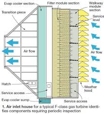
Components of Air Intake Filtration system:
- Air Intake Filter Hose
- At the entry point of air, there is moisture separator/ Weather hood.
- Access area OR Service area for fitting and inspecting the filter media.
- Filter module area – All filter modules are installed in this section.
- Clean air section – Air after filtration in the filter modules flows through this section to the GT Axial compressor.
- Safety net after clean air section is installed to prevent any foreign object to flow to the compressor.
- Heating section in the clean air side (Applicable for cold weather)
Ambient air quality testing is required at regular interval:
In order to ensure that the air intake filters are operating within the criteria set by the OEM or the user, it is very important to analyze the ambient air quality.
To have a representative record, ambient air quality to be tested every quarterly.
In general, following tests to be carried out in a certified laboratory.
However, power plants to decide on the tests to be conducted depending upon the demography and past environment records:
- Sulphur Di-oxide (SO2) – Test method IS 5182 (Part 02) : Reaff. 2006
- Nitrogen Di-oxide (NO2)- Test method IS 5182 (Part 06) : 2006
- Particulate matter (PM-10)- Test method IS 5182 (Part 23) :2006
- Particulate matter (PM-2.5)- Test method SO-IN-MUL-TE-068
- Ozone (O3)-Test method SO-IN-MUL-TE-075
- Ammonia(NH3)- Test method SO-IN-MUL-TE-075
- Methane- Test method IS 5182 (Part 17) : 1979
- Ethane - Test method IS 5182 (Part 17) : 1979
- Propane - Test method IS 5182 (Part 17) : 1979
- Butane - Test method IS 5182 (Part 17) : 1979
- Pentane - Test method IS 5182 (Part 17) : 1979
- Hydrogen Sulphide as H2S – Test method IS 5182 (Part 07) : 1973
- Hydrochloric acid as HCL – Test method NIOSH 7908
- Sulphuric acid as H2SO4- Test method NIOSH 7908
- Nitric acid as HNO3 - Test method NIOSH 7908
- Chlorine – Test method IS 5182 (Part 19) : 1982
Operational checks to be carried out:
- Check air intake filter DP across the filter house.
- Check pulse jet cleaning system is in service and on “Auto” mode of operation.
- Check air pressure for pulse jet cleaning system is “Adequate”.
- During pulsation check the “pulse pressure decay” and recovery time of the pressure.
- Check that the pulse jet cleaning sequence is correctly maintained.
- Check for any abnormal sound for pulse jet pipe or solenoid valve failure.
- Always cross check the DP from transmitter and local gauge.
- Check for any abnormal sound from the clean air side.
- After pulsation DP should come back to Pre-set level.
Conclusion:
It is very much important that Air Intake filter selection must be done with utmost care.
GT Axial compressor efficiency is the key performance parameter, as the higher the efficiency the lower the GT Heat Rate (HR).
Air quality testing at predefined interval must be in place to understand the life cycle of the Filters.
It is to be noted that any unscheduled shutdown of the plant is direct “Business loss” & hence must be prevented with good engineering, Operating & maintenance practice.
Bibek Roy
An experienced power plant professional having more than 34 years of experience in India & abroad. Certified Lead auditor for QMS, EHSMS. Certifed Energy auditor from BEE. A trainer, coach and auditor. An evangelist for sustainability.
READ THeSe NEXT
Energy and Water audit must go hand in hand in large commercial complexes.
Here is a short guide for achieving the same.
ENERGY EFFICIENCY A POWERFUL TOOL FOR dE-CARBONIZATION